Pioneer radio wire diagramterms of use – Pioneer Radio Wire Diagram: Terms of Use – Understanding your car stereo’s wiring is crucial for installation, repair, and modifications. This guide provides a comprehensive overview of Pioneer car radio wiring diagrams, covering various models, common symbols, troubleshooting techniques, and safety precautions. We’ll explore how to identify your specific radio model, decipher wiring diagrams, and safely address common wiring issues.
Whether you’re a seasoned car audio enthusiast or a novice DIYer, this resource will empower you to confidently work with your Pioneer car radio’s electrical system.
From identifying your Pioneer radio model and understanding its unique wiring characteristics to troubleshooting common problems and performing advanced modifications, this guide offers step-by-step instructions and clear explanations. We’ll delve into the intricacies of wiring diagrams, exploring their various sections and the symbols they employ. We’ll also cover essential safety procedures and legal considerations to ensure a safe and compliant installation or repair process.
Pioneer Radio Model Identification and Variations
Identifying your Pioneer car radio model is crucial for finding the correct wiring diagram and troubleshooting any issues. Pioneer produced a vast array of car stereos over the years, each with unique features and wiring configurations. Understanding the model variations and how to identify them will greatly simplify repairs and upgrades.
Pioneer Radio Model Number and Manufacturing Year Information
The following table provides a sample of common Pioneer car stereo models and their approximate manufacturing years. Note that this is not an exhaustive list, and the years may vary depending on regional releases. Always check the unit itself for the most accurate information.
| Model Number | Year(s) of Manufacture (Approximate) | Notable Features | Common Issues |
|---|---|---|---|
| DEH-P7000UB | 2005-2007 | USB input, MP3 playback, detachable faceplate | Faulty CD mechanism, button malfunctions |
| DEH-X8700BH | 2015-2017 | Bluetooth connectivity, MIXTRAX, detachable faceplate | Bluetooth connectivity problems, screen backlight issues |
| MVH-X590BT | 2019-2021 | Bluetooth connectivity, smartphone app compatibility, USB input | Intermittent power issues, aux input problems |
| AVH-X4900BS | 2018-2020 | Apple CarPlay and Android Auto compatibility, built-in navigation (some models), touchscreen display | Touchscreen responsiveness issues, navigation system glitches |
Variations in Pioneer Radio Wiring Diagrams
Wiring diagrams for Pioneer car stereos can vary significantly depending on the model and year of manufacture. Key differences often lie in connector types and pinouts.
Explore the different advantages of listcrawler fort worth texas that can change the way you view this issue.
Understanding these variations is essential for correct installation and to avoid damaging the unit or the vehicle’s electrical system. Incorrect wiring can lead to malfunctions or even damage to the stereo or vehicle electronics.
- Connector Types: Some models use ISO connectors, while others employ proprietary connectors. The number and arrangement of pins will differ accordingly.
- Pinouts: Even with the same connector type, the pin assignments for power, ground, speakers, and other functions can vary between models. Consulting the specific wiring diagram for your model is crucial.
- Additional Features: Models with features like navigation, amplifiers, or subwoofer outputs will have additional wires and connectors compared to simpler units.
- Amplifier Integration: Some models integrate amplifiers internally, while others require external amplifiers. This significantly affects the wiring configuration.
Identifying a Pioneer Radio Model
Identifying the precise model of a Pioneer radio involves examining its physical characteristics and markings.
Accurate identification is key to finding the correct information, such as the wiring diagram, user manual, and troubleshooting guides. Incorrect identification can lead to wasted time and potential damage to the equipment.
- Model Number: Look for a sticker or label on the unit itself, typically located on the front or back. The model number will be clearly printed, often preceded by “DEH,” “MVH,” “AVH,” or similar prefixes.
- Serial Number: The serial number is also helpful, especially when contacting Pioneer support or searching for information online. It can provide additional details about the unit’s manufacturing date and specifications.
- Physical Features: Pay attention to the size, shape, display type (LCD, LED, touchscreen), and the presence of specific features (e.g., USB port, CD player, auxiliary input). These characteristics can help narrow down the possible models.
- Faceplate: If the radio has a detachable faceplate, the model number might be printed on the faceplate itself.
Understanding Pioneer Radio Wiring Diagrams: Pioneer Radio Wire Diagramterms Of Use

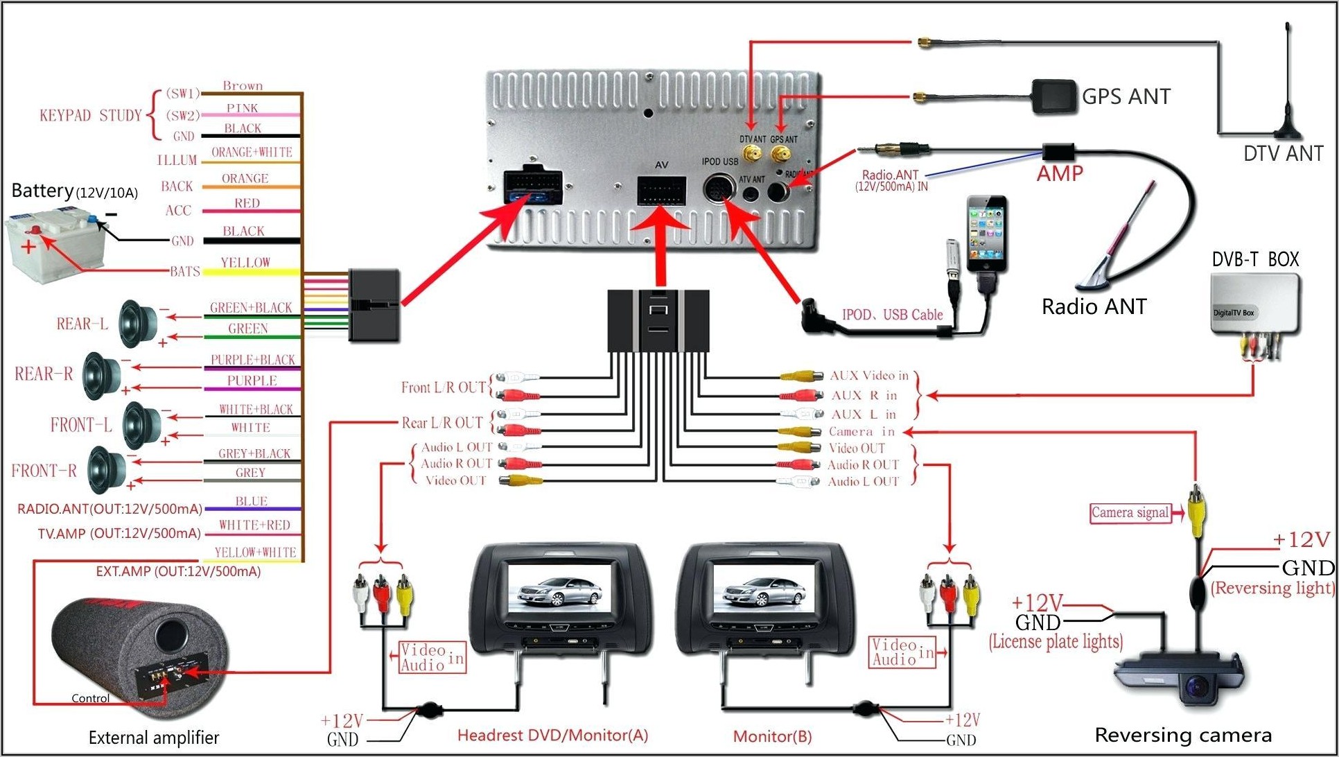
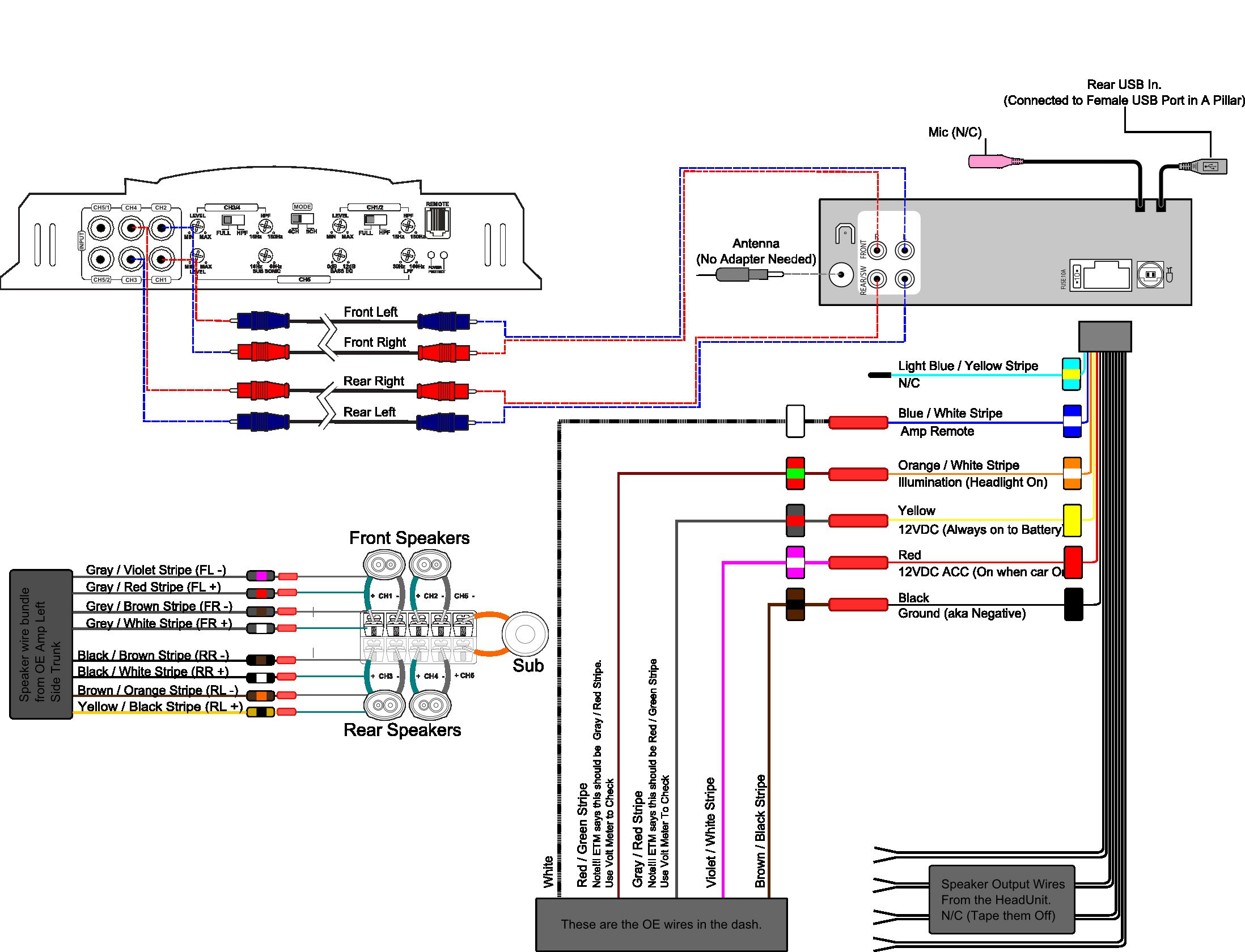
Pioneer car radio wiring diagrams are essential for installation and troubleshooting. Understanding the symbols, sections, and overall structure of these diagrams simplifies the process significantly, allowing for efficient and accurate connections. This section will detail the common elements found in Pioneer radio wiring diagrams, helping you navigate them with ease.
Common Symbols and Notations, Pioneer radio wire diagramterms of use
Wiring diagrams utilize standardized symbols to represent different components and connections. This ensures clarity and consistency across various models. Familiarity with these symbols is crucial for accurate interpretation of the diagram. The following table lists some common symbols and their meanings:
| Symbol | Meaning |
|---|---|
| + | Positive (+) wire connection |
| – | Negative (-) wire connection |
| GND | Ground connection |
| ||| | Speaker connection |
| ~ | Antenna connection |
| □ | Relay |
| ○ | Fuse |
| ∧ | Illumination wire |
| (various colored lines) | Specific wire designation (refer to legend) |
Sections of a Typical Pioneer Radio Wiring Diagram
A typical Pioneer car radio wiring diagram is organized into distinct sections, each representing a specific aspect of the radio’s electrical system. These sections typically include:
The Power Section shows connections for the constant power (+12V), switched power (+12V switched with ignition), and ground. These connections are crucial for powering the radio and ensuring its proper operation.
The Speaker Section details the connections for the left and right front and rear speakers. This section typically includes the positive and negative wires for each speaker, and may indicate impedance ratings.
The Antenna Section illustrates the connection for the car’s antenna. This connection ensures the radio receives signals effectively.
The Illumination Section depicts the connection for the radio’s illumination light, which allows the radio’s buttons and display to be lit up at night.
An Accessory Section may be present, detailing connections for features like remote controls or amplifier connections. These connections vary greatly depending on the model and specific features of the Pioneer radio.
Simplified Generic Wiring Diagram
The following is a simplified, generic wiring diagram for a basic Pioneer car radio. Note that this is a generic representation and specific wire colors and configurations may vary depending on the model. Always refer to the specific wiring diagram for your Pioneer radio model.
Imagine a diagram showing a rectangular box representing the Pioneer car radio. From this box, several wires extend. A thick red wire labeled “+12V Constant” connects to the battery’s positive terminal. A thick black wire labeled “GND” connects to the chassis ground. A thinner red wire labeled “+12V Switched” connects to the ignition’s switched power source.
Four pairs of wires (two pairs for front speakers, two pairs for rear speakers) labeled “Left Front (+/-),” “Right Front (+/-),” “Left Rear (+/-),” and “Right Rear (+/-),” connect to the respective speaker wires. A wire labeled “Antenna” connects to the car’s antenna. Finally, a thinner yellow wire labeled “Illumination” connects to the car’s illumination circuit.
Troubleshooting Common Wiring Issues

Installing or repairing a Pioneer car radio can sometimes present wiring challenges. Understanding common problems and effective diagnostic techniques is crucial for a successful installation and optimal audio performance. This section will guide you through identifying, diagnosing, and resolving typical wiring issues.
Common wiring problems during Pioneer car radio installation or repair frequently stem from incorrect connections, damaged wires, or faulty components. These issues can manifest in various ways, from complete audio silence to distorted sound or even electrical malfunctions within the vehicle.
Common Wiring Problems
Several recurring problems plague Pioneer car radio installations. Addressing these issues proactively minimizes frustration and ensures a smooth installation process.
- Incorrect speaker wire connections: This is a very common problem, leading to no sound or out-of-phase sound (where sounds are canceling each other out).
- Power wire connection errors: Incorrectly connecting the power wires can result in a blown fuse, a non-functioning radio, or even damage to the vehicle’s electrical system.
- Ground wire issues: A poor ground connection will lead to intermittent audio, static, or even complete failure of the radio.
- Short circuits: These can occur due to frayed wires, improper insulation, or accidental contact between wires, potentially damaging the radio or the vehicle’s electrical system.
- Antenna connection problems: A loose or faulty antenna connection will result in poor or no radio reception.
- Illumination wire issues: Improper connection of the illumination wire can lead to the radio’s display not lighting up correctly or not at all.
Diagnosing Wiring Faults with a Multimeter
A multimeter is an invaluable tool for diagnosing electrical problems. Its ability to measure voltage, current, and resistance allows for precise identification of wiring faults.
- Visual Inspection: Begin by visually inspecting all wires for any signs of damage, such as cuts, fraying, or exposed conductors. Pay close attention to the connections at both ends of each wire.
- Voltage Checks: Use the multimeter’s voltage setting (DC voltage is typically used for automotive applications) to check the voltage at various points in the circuit. Compare your readings to the radio’s wiring diagram to ensure the correct voltages are present. For example, check the voltage at the constant power wire (+12V), the switched power wire (+12V when the ignition is on), and the ground wire (0V).
- Continuity Testing: Use the multimeter’s continuity test function to check for breaks in the wiring. Place the multimeter leads on each end of the wire; a continuous tone indicates a good connection. A lack of tone indicates a broken wire.
- Resistance Checks: This step is useful for checking the integrity of speakers and other components. Disconnect the speaker wires and measure the resistance across the speaker terminals. A high resistance indicates a faulty speaker.
Correcting Common Wiring Errors
Once a wiring fault is identified, correcting it requires careful attention to detail and adherence to safety procedures.
- Incorrect Speaker Polarity: If the sound from a speaker is reversed or distorted, check the speaker wire connections. Ensure that the positive (+) and negative (-) wires are connected correctly to the speaker and the radio. Swapping the wires will correct the polarity.
- Short Circuits: If a short circuit is detected, carefully isolate the affected section of wiring. Repair damaged insulation, replace faulty wires, and ensure that no wires are touching each other. A visual inspection may not always be enough; using a multimeter can help pinpoint the location of the short circuit.
- Poor Ground Connection: A poor ground connection can manifest as intermittent audio, static, or complete radio failure. Ensure that the ground wire is securely connected to a clean, unpainted metal surface on the vehicle’s chassis. If necessary, clean the ground point with sandpaper or a wire brush to improve conductivity.
Mastering your Pioneer car radio’s wiring unlocks a world of customization and repair possibilities. By understanding the diagrams, troubleshooting techniques, and safety procedures Artikeld in this guide, you can confidently tackle various projects, from basic installations to advanced modifications. Remember to always prioritize safety and adhere to relevant legal regulations. With the knowledge gained here, you can enjoy a seamless and safe audio experience in your vehicle.


